
Topographic Survey: Conventional and Modern Methods
Syfujjaman
Wednesday, April 03, 2024
0 Comments

A topographic survey is a fundamental technique used in various fields such as civil engineering, land development, urban planning, and environmental management and cartography. It involves the measurement and mapping of the physical features of a landscape, including its natural and man-made characteristics. The primary goal of a topographic survey is to accurately represent the three-dimensional surface of the Earth, capturing details such as elevation, contour lines, vegetation, water bodies, buildings, roads, and other infrastructure.
Topographic surveying encompasses a diverse array of methods and techniques for mapping the Earth's surface features. While conventional methods such as chain surveying and plane table surveying have a long history and remain relevant for certain applications, modern surveying technologies offer significant advantages in terms of accuracy, efficiency, and data quality. GPS/GNSS, LiDAR, UAVs, and remote sensing have revolutionised the field of topographic surveying, enabling surveyors to capture detailed terrain data over large areas with unprecedented precision. By leveraging the strengths of both conventional and modern methods, surveyors can meet the diverse needs of clients and stakeholders across various industries, from civil engineering and land development to environmental management and emergency response.
History of Topographic Surveying
The history of topographic surveying dates back centuries, evolving alongside advancements in surveying techniques and technology. Early civilizations such as the Egyptians, Greeks, and Romans used rudimentary methods to map their territories for administrative, military, and economic purposes. These methods often involved simple tools such as ropes, rods, and rudimentary measuring instruments.
Over time, the development of more sophisticated surveying instruments, such as the theodolite and the total station, revolutionised the field of topographic surveying. These instruments allowed for more accurate measurements of angles and distances, enabling surveyors to create detailed maps with precise elevation data. The advent of satellite technology, particularly GPS (Global Positioning System), further enhanced the accuracy and efficiency of topographic surveys by providing precise positioning information from space.
Principles of Topographic Surveying
Topographic surveying has two fundamental parts:
1. The horizontal measurements for making ground plan and setting up offsets. Traversing, triangulation etc. are used to prepare the ground plan, and
2. The vertical measurements for determining the height or elevation of points from MSL (Datum).
In order to complete the entire topographic survey there are several fundamental principles to follow to ensure the accuracy and reliability of the collected data:
- Control Points: Establishing a network of control points across the survey area is crucial for georeferencing and spatial accuracy. These points serve as reference markers with known coordinates, allowing surveyors to accurately position their measurements relative to a common coordinate system.
- Traversing and triangulation: Traversing involves the sequential measurement of distances and angles between control points to establish the framework for the survey. By carefully traversing the survey area, surveyors can ensure that their measurements are connected and consistent, minimising errors in the final map.
- Setting up vertical Datums: Topographic surveys include elevation data, which requires a consistent vertical datum for accuracy. Common vertical datums include mean sea level (MSL) and local datums established based on nearby benchmarks. Surveyors must accurately reference elevation measurements to the chosen datum to ensure compatibility with other geospatial data.
- Data acquisition: Capturing the natural and man-made features of the terrain is a central aspect of topographic surveying. Surveyors use various methods, including direct measurements, photogrammetry, LiDAR (Light Detection and Ranging), and remote sensing, to collect data on elevation, vegetation, water bodies, and infrastructure.
- Data Accuracy and Precision: Topographic surveys require high levels of accuracy and precision to produce reliable maps and models. Surveyors must carefully calibrate their instruments, account for measurement errors, and apply appropriate quality control measures to ensure the integrity of the collected data. Various checks are performed with the collected data to ensure accuracy in the data.
- Terrain Representation: after all the necessary correction and checks of the data, the terrain is represented through conventional cartographic symbols. Colour coding is used in the small scale maps for general purpose. Contours are drawn to accurately portray the elevation parameters.
Topographic surveying, a critical aspect of geospatial data collection and mapping, utilises various conventional and modern methods to accurately represent the Earth's surface features. These methods have evolved over time, incorporating advancements in technology, instrumentation, and data processing techniques.
Conventional Methods of Topographic Surveying
Step-1: Horizontal measurements for making ground plans.
1. Chain Surveying
Chain surveying is a traditional method of land surveying that has been used for centuries to map and measure the features of a piece of land. It is a simple and straightforward technique that involves the use of basic equipment and manual measurements to determine the positions of various points on the ground. In this method, a chain or tape is used to measure distances, while other tools such as ranging rods and arrows help in aligning and marking survey points.
It is particularly suited for small, relatively flat areas with simple terrain features. Despite its simplicity, chain surveying can yield accurate results when performed carefully.
Principles of Chain Surveying
The fundamental principle of chain surveying is to establish a network of accurately measured reference points, known as survey stations, across the survey area. These stations serve as the basis for conducting linear measurements and creating a detailed map of the terrain. By connecting these stations with measured distances and angles, surveyors can delineate the boundaries, features, and contours of the land.
Equipment Used in Chain Surveying
- Chain or Tape: The primary instrument for measuring distances in chain surveying is a chain or tape. Chains are typically made of metal links, with each link measuring a specific length, such as 20 metres or 66 feet. Tapes are flexible measuring devices made of materials like steel or fibreglass and come in various lengths.
- Ranging Rods: Ranging rods are used to mark survey stations and provide visual reference points for alignment during the survey. They are usually made of wood or metal and are painted in bright colours for easy visibility.
- Arrows: Arrows or flags are placed at survey stations to mark their positions and aid in sighting and alignment during measurements.
- Cross Staff: A cross staff is a simple instrument used for setting perpendicular offsets. It consists of two perpendicular arms with sights at each end, allowing surveyors to align with survey lines and locate objects at right angles.
The process of conducting a chain survey typically involves the following steps:
- Reconnaissance: Before starting the survey, surveyors conduct a preliminary inspection of the area to be surveyed. They study maps, aerial photographs, and other available data to familiarise themselves with the terrain and plan the survey.
- Marking Survey Stations: Survey stations are established at key points across the survey area using ranging rods or other markers. These stations should be visible from one another and strategically located to ensure comprehensive coverage of the land.
- Setting Baseline: A baseline is a straight line that serves as the primary reference for measuring distances and angles during the survey. Surveyors select a suitable baseline that passes through the centre of the survey area and extends to its boundaries.
- Measuring Distances: Using a chain or tape, surveyors measure distances between survey stations along the baseline and other reference lines. Each measurement is recorded carefully to ensure accuracy.
- Setting Offsets: Perpendicular offsets are measurements taken from the baseline to locate objects or features that are not directly on the survey line. Surveyors use cross staffs or other instruments to set perpendicular offsets accurately.
- Recording Data: All measurements, observations, and other relevant data are recorded in a field book. Sketches, notes, and annotations are often included to provide additional context and clarity.
- Calculating and Plotting: Back in the office, surveyors process the collected data, calculate distances, angles, and elevations, and plot them on a map or plan. The resulting topographic map represents the terrain features, boundaries, and contours of the survey area.


Chain surveying has a wide range of applications in various fields, including:
- Land Development: Chain surveying is used to determine property boundaries, plot sizes, and land ownership rights for urban and rural development projects.
- Civil Engineering: Engineers use chain surveying to plan and design infrastructure projects such as roads, bridges, pipelines, and drainage systems.
- Mapping and Cartography: Chain surveying provides essential data for creating accurate maps, charts, and plans for navigation, resource management, and land-use planning.
- Construction: Chain surveying helps construction professionals to layout building sites, excavations, foundations, and other structures accurately.
- Environmental Management: Survey data is used to assess and monitor environmental changes, such as deforestation, erosion, and habitat loss, and to develop conservation and restoration strategies.
Advantages:
- Simplicity: Chain surveying is a straightforward technique that requires minimal equipment and training, making it accessible to a wide range of surveyors.
- Accuracy: With careful measurements and proper techniques, chain surveying can produce accurate results suitable for many applications.
- Cost-Effectiveness: Chain surveying is relatively inexpensive compared to modern surveying methods, making it suitable for small-scale projects and budget-conscious clients.
- Labour-Intensive: Chain surveying can be time-consuming and labour-intensive, especially for large or complex survey areas.
- Limited Accuracy: While chain surveying can provide accurate results under ideal conditions, it may be less precise than modern surveying techniques, especially over rugged or uneven terrain.
- Manual Errors: Human errors such as incorrect measurements, misalignment, and data recording mistakes can occur during chain surveying, affecting the overall accuracy of the results.
Plane table surveying is a graphical method of surveying used to create plans/ maps of small areas directly in the field. Surveyors mount a drawing board, or plane table, on a tripod and orient it to true north using a compass. They then sketch the features of the terrain onto a sheet of paper mounted on the table, referencing distances and angles measured with a chain or tape and a compass or theodolite.
Plane table surveying requires skilled operators and is relatively slow compared to modern techniques but can produce accurate maps in real-time.
Principles of Plane Table Surveying
The fundamental principle of plane table surveying is to create a graphical representation of the terrain features directly on a flat surface, such as a drawing board. This allows surveyors to visualise and record the positions of various points, lines, and features of the land accurately. By orienting the plane table to true north using a compass, surveyors can ensure that their sketches align with the actual geographic directions.

Equipment Used in Plane Table Surveying
Plane Table: The central piece of equipment in plane table surveying is the plane table itself. It is essentially a drawing board mounted on a tripod, allowing it to be positioned and levelled at different locations across the survey area.
Tripod: The tripod provides support for the plane table, allowing it to be positioned at different heights and angles. It is adjustable to ensure stability and proper alignment during the survey.
Alidade: An alidade is a sighting device mounted on the plane table, consisting of a straightedge with a sight or telescope at one end. It is used to sight distant objects and lines of sight, enabling surveyors to determine the positions and directions of various features.
U-Frame with Plumbob: The U-frame is a U-shaped frame, used for centering the point on the paper with the ground point.
Trough Compass: Compass within a trough shaped wooden case is used for indicating the North meridian.
Spirit Level: This is a small tube filled with liquid, used for levelling the plane table.
Ranging Rod: This is the metalled rod used for bisection to orient the lines on the paper with the ground.
Ground Pin: These are the metalled pins used for marking the ground points.
Drawing Instruments: Surveyors use various drawing instruments, such as pencils, pens, rulers, protractors, and triangles, to sketch and annotate the features of the terrain on the plane table.


Procedure of Plane Table Surveying
The process of conducting a plane table survey typically involves the following steps:
Station Setup: Surveyors select a suitable location for the plane table station, ensuring that it provides a clear view of the surrounding terrain without any obstruction. The tripod is positioned on stable ground, and the plane table is levelled using a spirit level to ensure accuracy. U-Frame is used to coincide the point of the paper with the ground station over which the plane table is positioned.
Orientation: Once the plane table is set up, surveyors orient it to true north using a trough compass or by aligning it with known reference points. This ensures that the sketches and measurements taken on the plane table correspond to the actual geographic directions.
Sighting and Sketching: Using the alidade, surveyors sight distant objects or reference points and sketch their positions on the plane table. They may also sketch prominent features of the terrain, such as roads, rivers, buildings, and topographic contours, based on visual observation or measurements taken with other instruments.
Relocation: After sketching the features visible from the current station, surveyors relocate the plane table to another station and repeat the process. By moving to different vantage points and sketching overlapping views, surveyors can create a comprehensive map of the entire survey area.
Field Notes: Throughout the survey, surveyors record detailed field notes, including descriptions of features, measurements, observations, and any other relevant information. These notes serve as a record of the survey and provide context for the final map or plan.
Compilation: Back in the office, surveyors compile the sketches and field notes collected during the survey into a cohesive map or plan. They may refine the sketches, add annotations, and incorporate additional data to create a finalised representation of the terrain.
Applications of Plane Table Surveying
Plane table surveying has a wide range of applications in various fields, including:
Topographic Mapping: Plane table surveying is commonly used to create detailed topographic maps of terrain features, including elevation contours, vegetation, and man-made structures.
Engineering Design: Engineers use plane table surveying to gather data for infrastructure projects, such as roads, railways, pipelines, and utility networks. The detailed maps produced by plane table surveying help in the design and planning of these projects.
Land Management: Plane table surveying is used in land management activities, such as land-use planning, environmental conservation, and natural resource management. The maps created through plane table surveying provide valuable information for decision-making and policy development.
Disaster Management: Plane table surveying is employed in disaster management efforts, such as assessing damage after natural disasters, planning evacuation routes, and identifying areas at risk of flooding or landslides.
Archaeological Surveying: Archaeologists use plane table surveying to map archaeological sites and document the locations of artefacts, features, and structures. The detailed maps produced by plane table surveying aid in the study and interpretation of archaeological remains.
Advantages and Limitations of Plane Table Surveying
Advantages:
Simplicity: Plane table surveying is a straightforward and intuitive method that requires minimal equipment and training. It allows surveyors to create detailed maps directly in the field without the need for complex instruments or software.
Real-Time Mapping: Plane table surveying enables surveyors to create maps in real-time, allowing for immediate visualisation and analysis of the terrain features. This can be particularly useful for rapid assessment and decision-making in fieldwork.
Versatility: Plane table surveying can be used in a wide range of environments and conditions, including remote or inaccessible areas where other surveying methods may be impractical or costly.
Limitations
Limited Accuracy: While plane table surveying can provide accurate maps under ideal conditions, its accuracy may be affected by factors such as instrument error, human error, and environmental conditions. This may limit its suitability for certain applications requiring high precision.
Time-Consuming: Plane table surveying can be time-consuming, especially for large or complex survey areas. The process of relocating the plane table to multiple stations and sketching overlapping views requires patience and attention to detail.
Subjectivity: The accuracy and quality of the maps produced by plane table surveying may vary depending on the skill and experience of the surveyor. Subjective factors such as interpretation of terrain features and sketching techniques may influence the final results.
3. Prismatic Compass Traversing
Prismatic compass traversing is a traditional method of land surveying used to determine the direction and distance between survey points. It involves the use of a prismatic compass, a simple and portable instrument that combines a magnetic compass with a sighting device, to measure angles and traverse between survey stations. Prismatic compass traversing has been widely employed for centuries due to its simplicity, reliability, and suitability for small-scale surveys in areas with limited access or rugged terrain.
Components of a Prismatic Compass
Before delving into the details of prismatic compass traversing, it's important to understand the components of a prismatic compass:
Compass Dial: The compass dial is a circular scale divided into degrees, with a magnetic needle or card mounted at its centre. It indicates the direction of magnetic north and allows surveyors to measure azimuth angles (bearings) relative to a reference direction.
Sighting Device: The prismatic compass is equipped with a sighting device, typically a sighting van or alidade, which provides a line of sight for aligning the compass with distant survey points. The sighting device allows surveyors to aim the compass accurately and read angles with precision.
Prism: A prism is mounted on the compass dial, allowing surveyors to read the bearing or azimuth angle directly through the eyepiece of the sighting device. The prism facilitates easy and accurate angle measurements in the field.
Tripod: The tripod provides support for the plane table, allowing it to be positioned at different heights and angles. It is adjustable to ensure stability and proper alignment during the survey.
Spirit Level: This is a small tube filled with liquid, used for levelling the compass.
Ranging Rod: This is the metalled rod used for bisection to orient the instrument with lines on the ground.
Ground Pin: These are the metalled pins used for marking the ground points.
Procedure of Prismatic Compass Traversing:
The process of conducting a prismatic compass traverse involves several sequential steps:
Station Setup: Surveyors begin by selecting a starting station or control point from which to initiate the traverse survey. The prismatic compass is set up at this station and levelled using a bubble level.
Bisection and Orientation: Once the compass is levelled, surveyors orient it to the first survey line by rotating the compass dial and bisection using the ranging rod.
Sighting and Angle Measurement: With the compass properly oriented, surveyors sight through the prism to the next survey point and measure the azimuth angle from the compass dial. The angle is read directly using the prism through the eyepiece of the sighting device.
Distance Measurement: In addition to measuring angles, surveyors also measure the distance between the instrument and the survey point using various methods such as pacing, taping, or electronic distance measurement (EDM) devices. The measured distance is recorded along with the corresponding azimuth angle.
Traversing: After measuring the angle and distance to the first survey point, surveyors move the compass to the next station along the traverse line. This process is repeated for each successive station, with the instrument being reoriented and levelled at each new location.
Closing the Traverse: Once all survey points have been measured, surveyors return to the starting point of the traverse and reoccupy the initial station. They then re-measure the azimuth angle to the starting point to check for closure errors and ensure the accuracy of the traverse.
Calculations: Back in the office, surveyors process the data collected during the traverse survey and perform calculations to adjust for any errors and inconsistencies. This may involve computing corrections for angular and distance measurements, adjusting for instrument and observational errors, and reconciling any discrepancies in the traverse closure.
Mapping: The final step of the prismatic compass traverse survey is to use the processed data to create a detailed map or plan of the surveyed area. This map typically includes the positions of survey points, as well as other features such as boundaries, topographic contours, and relevant infrastructure.
Terminologies:
Bearing- it is the horizontal angle formed by a line with a reference meridian in clockwise direction.
Types:
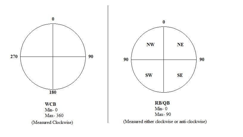
WCB- (Whole Circle Bearing): When bearing measured in whole circle format clockwise.
QB/RB- (Quadrantal or reduced Bearing): when the bearing is measured in quadrantal form in which the bearing is measured from the north-south meridian either clockwise or anti-clockwise. (See figures below)
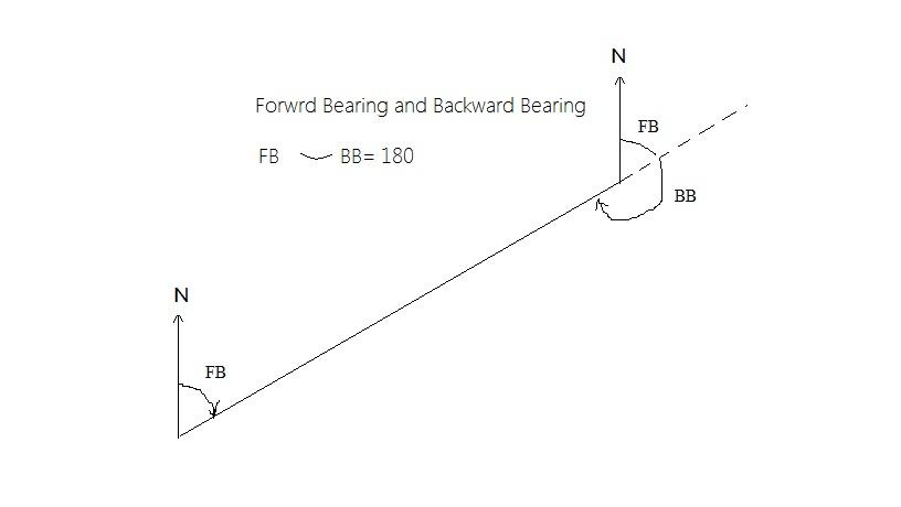
Forward Bearing and Backward Bearing: FB is the bearing measured in the direction of the progress of the survey. BB is measured in the opposite direction to the progress of the survey. (see figures below)
Based on the reference line used, bearing can be of three types-
Arbitrary Bearing; when bearing is measured from an arbitrary reference line, it is called arbitrary bearing.
Magnetic bearing: when bearing is measured from the magnetic meridian, it is known as magnetic bearing.
True bearing: when bearing is measured from the geographical meridian of longitude, it is called geographical bearing.
Traversing by prismatic Compass:
A traverse survey is one in which the framework consists of a series of connected lines, the lengths and directions of which are measured with a tape and angular instrument respectively.
Prismatic compass can be used to measure the angular distance of objects from a reference line i.e. magnetic meridian.
For traversing the forward and backward bearings are taken for each line of the traverse. Distances are measured by measuring tape. All the readings are noted in a field book.
Plotting of traverse: traverse can be plotted in two ways-
Parallel Meridian method: at each point the lines are plotted according to their lengths (on a scale) and bearings measured from magnetic meridian which is parallel in every station.
Included angle method: first the included angles are calculated from the bearings. Then the first line is plotted based on the bearing and length. The next lines are plotted according to the included angles they form at each station.
Included angle= BB of the preceding line FB of the forwarding line.
If Quadrantal Bearing is given, the included angle will be in the following manner:
If the lines lie in the same quadrant, the included angle is simply the difference between the two Quadrantal bearings.
If the line lies in the two adjacent quadrants on the same side of the meridian, the included angle is = (180 – sum of the two reduced bearings).
If the line lies in the two adjacent quadrants on the opposite sides of the meridian, the included angle is simply the sum of the two Quadrantal bearings.
If the lines lie in the two distant quadrants (diagonally opposite), the included angle is = (1800 – difference of the two Quadrantal bearings).
Excluded angle= 3600 – included angle.
Error corrections:
If the difference between FB and BB is not 1800 it is called as error.
If the error is negative (<1800), then deduct error/2 from smallest values and add error/2 with largest values.
If the difference is positive (>1800), then add error/2 with smallest values and deduct error/2 from largest values.
Correction of closed traverse:
Sometimes the initial and end point do not coincide during the plotting of traverse. The gap between the initial and end point is called the closing error. This error can be distributed graphically by adjusting the lengths and bearings following Bowditch’s method. The principle of Bowditch’s method is ‘the magnitude of error is proportional to the square root of distance.’
Correction of included angles:
Sum of the internal angles: n= (2n-4)*900 (n= number of sides)
Sum of the external angles: n= (2n+4)*900 (n= number of sides)
Sum of deflection angles: n= 3600 (deflection angle= 180 degree - included angle)
WCB of a line = WCB of preceding line ± d (d= deflection angle)
Source of error of prismatic compass survey:
The common sources of error of prismatic survey can be categorised as under-
Instrumental errors: Instrumental errors are-
magnetic needle is not perfectly straight or sluggish,
lost of magnetism,
needle may be freely moving,
pivot is dull or bent,
plane of sight is not vertical
line of sight is not passing through the centre of the graduated circle,
vertical hair is thick or loose etc.
Human or observation error: Observation errors are-
improper centering,
improper levelling,
imperfect bisection,
carelessness in reading the graduated circle,
improper recording of the readings etc.
External influences: External influences in the prismatic compass survey are-
Magnetic change in the atmosphere,
Variation in magnetic declination,
Local attractions due to proximity of the magnetic substances etc.
Applications of Prismatic Compass Traversing:
Prismatic compass traversing has been widely used in various fields for a range of applications, including:
Small-Scale Surveys: Prismatic compass traversing is suitable for small-scale surveys in areas with limited access or rugged terrain, where other surveying methods may be impractical or costly.
Exploratory Surveys: Prismatic compass traversing is often used in exploratory surveys to map the general layout and features of an area before conducting more detailed surveys.
Boundary Surveys: Prismatic compass traversing is employed to establish property boundaries, delineate land parcels, and resolve boundary disputes.
Geological Surveys: Prismatic compass traversing is used in topographic and geological surveys to map rock outcrops, structural features, and geological formations in the field.
Archaeological Surveys: Prismatic compass traversing is employed in archaeological surveys to map archaeological sites and document the locations of artefacts, features, and structures.
Advantages and Limitations of Prismatic Compass Traversing
Advantages
Portability: Prismatic compasses are lightweight and portable, making them easy to carry and set up in the field. They are suitable for surveys in remote or inaccessible areas where other surveying methods may be impractical.
Simplicity: Prismatic compass traversing is a simple and straightforward method that requires minimal equipment and expertise. It can be performed by a single surveyor with basic training in compass use and surveying techniques.
Reliability: Prismatic compasses are robust and reliable instruments that are not affected by electronic interference or battery failure. They can be used in various environmental conditions, including adverse weather and rugged terrain.
Limitations
Limited Accuracy: Prismatic compass traversing may have limitations in terms of accuracy, especially over long distances or in areas with magnetic anomalies or irregularities. Errors may occur due to magnetic declination, instrument calibration, or observational factors.
Manual Measurements: Prismatic compass traversing relies on manual measurements of angles and distances, which can be subject to human error and inconsistencies. Surveyors must exercise caution and diligence to ensure the accuracy of their measurements.
Limited Features: Prismatic compasses lack some of the advanced features and capabilities of modern surveying instruments, such as electronic data recording, automatic levelling, and real-time positioning. They may be less suitable for surveys requiring high precision or advanced mapping techniques.
Theodolite Traversing
Theodolite traverse is a method for establishing control points and measuring angles and distances across a survey area. Surveyors set up a theodolite at each control point and measure horizontal and vertical angles to adjacent points. Distances between points are measured using a chain, tape, or EDM (Electronic Distance Measurement). The data collected during the traverse is used to compute the coordinates and elevations of surveyed points, forming the basis for creating topographic maps.
This method is commonly used in civil engineering, construction, geodetic mapping, and other surveying applications due to its accuracy and versatility.
Components of a Theodolite
Before discussing the procedure of theodolite traversing, it's important to understand the components of a theodolite:
The process of conducting theodolite traversing involves several sequential steps:
Theodolite traversing has a wide range of applications in various fields, including:
Advantages
Levelling is a technique used to determine the elevations of points on the Earth's surface relative to a reference datum, such as mean sea level. Surveyors use a levelling instrument, such as a dumpy level or a digital level, to measure the height difference between benchmark points. By establishing a series of level loops and tying them into the control network, surveyors can accurately determine the topography of the survey area and create contour lines representing changes in elevation.
1. Levelling by dumpy level
Dumpy level surveying is a traditional and widely used method for measuring height differences or elevations on the surface of the Earth. It is commonly employed in construction, civil engineering, land development, and other related fields to establish precise level lines and determine the relative heights of different points on a site. The dumpy level, also known as an automatic level or builder's level, is the primary instrument used in this surveying method. It consists of a telescope mounted on a horizontal axis and equipped with a built-in levelling mechanism to ensure accuracy.
Components of a Dumpy Level
Before delving into the details of dumpy level surveying, it's important to understand the components of a dumpy level:
The process of conducting a dumpy level survey involves several sequential steps:
Dumpy level surveying has a wide range of applications in various fields, including:
Advantages:
Modern methods of land and topographic surveying comprises both land based survey equipment and remote sensing techniques.
1. Total Station Surveying
Total station surveying is a land-based survey equipment, combining electronic theodolites with electronic distance measurement (EDM) technology to measure angles and distances with high precision. Total stations can be equipped with reflectorless EDM capabilities, allowing surveyors to measure distances to objects without requiring a prism. By conducting traverses and collecting detailed measurements of terrain features, surveyors can efficiently generate topographic maps with accurate elevation data.
Components of a Total Station
Before delving into the details of total station surveying, it's important to understand the components of a total station:
The process of conducting total station surveying involves several sequential steps:
Total station surveying has a wide range of applications in various fields, including:
Advantages
Remote sensing technologies, such as satellite imagery and aerial surveys, provide valuable data for topographic mapping and analysis. Advanced satellite sensors capture multispectral imagery and elevation data, allowing for the creation of detailed topographic maps and terrain models over large geographic areas. Aerial surveys, conducted using manned aircraft or UAVs, offer higher spatial resolution and can be tailored to specific survey requirements, making them suitable for a wide range of applications, from urban planning to natural resource management.
Aerial Photogrammetry
Photogrammetry is a technique for deriving topographic information from overlapping aerial photographs. Surveyors capture stereo pairs of aerial images using specialised cameras mounted on aircraft or drones. These images are processed using photogrammetric software to extract three-dimensional coordinates of ground points, allowing for the creation of digital elevation models (DEMs), orthophotos, and detailed topographic maps. Photogrammetry is particularly useful for large-scale mapping projects covering extensive areas.
1. GPS/GNSS Surveying
Global Positioning System (GPS) or Global Navigation Satellite System (GNSS) surveying utilises satellite signals to determine precise three-dimensional positions on the Earth's surface. Surveyors use GNSS receivers to collect position data at control points distributed across the survey area. By processing the collected data with specialised software, surveyors can establish accurate georeferenced control networks and collect spatial data for creating topographic maps, without the need for extensive ground-based measurements.
3. LiDAR (Light Detection and Ranging)
LiDAR is a remote sensing technology that uses laser pulses to measure distances to the Earth's surface. Airborne LiDAR systems emit laser beams and record the time it takes for the pulses to return after hitting the ground. By scanning the terrain from aircraft or drones, LiDAR produces highly detailed point clouds representing the surface topography. These point clouds can be processed to create high-resolution DEMs, contour maps, and 3D terrain models with exceptional accuracy and detail.
4. UAV/Drones
Unmanned Aerial Vehicles (UAVs), commonly known as drones, have emerged as versatile platforms for topographic surveying and mapping. Equipped with cameras, LiDAR sensors, or other remote sensing instruments, drones can capture high-resolution imagery and terrain data over small to medium-sized areas. Surveyors use specialised software to process drone-collected data and generate orthophotos, DEMs, and 3D models for various applications, including infrastructure planning, land development, and environmental monitoring.
Comparative Analysis
Accuracy and Precision
Modern methods of topographic surveying, such as GPS/GNSS, LiDAR, and UAVs, generally offer higher accuracy and precision compared to conventional techniques like chain surveying and plane table surveying. GNSS receivers and total stations can provide sub-centimeter-level positioning accuracy, while LiDAR and drone-based surveys can capture terrain features with millimetre-level detail. This increased accuracy is essential for engineering design, construction planning, and other applications requiring precise spatial data.
Efficiency and Productivity
Modern surveying methods are typically more efficient and productive than conventional techniques, enabling surveyors to cover larger areas in less time. GPS/GNSS surveying allows for rapid data collection across vast expanses of terrain, while LiDAR and UAV surveys can capture detailed topographic data over large areas in a fraction of the time required for ground-based surveys. The automation and integration capabilities of modern surveying technologies streamline data processing workflows, further enhancing survey efficiency and productivity.
Cost and Accessibility
Conventional surveying methods, such as chain surveying and plane table surveying, often require minimal equipment and can be performed by skilled labourers with basic training. As such, they tend to be more accessible and cost-effective for small-scale projects or in resource-constrained environments. In contrast, modern surveying technologies like GPS/GNSS, LiDAR, and UAVs may involve higher upfront costs for equipment, software, and training. However, the long-term benefits of improved accuracy, efficiency, and data quality may justify the investment, particularly for large-scale or high-precision projects.
Terrain and Environmental Considerations
Both conventional and modern surveying methods have advantages and limitations depending on the terrain and environmental conditions of the survey area. Conventional methods may be more suitable for rough or inaccessible terrain where direct line-of-sight measurements are challenging. However, they may require significant fieldwork and be subject to human error. Modern methods, such as LiDAR and UAV surveys, offer the advantage of remote data collection, making them well-suited for mapping rugged or environmentally sensitive areas. LiDAR, in particular, can penetrate dense vegetation and provide accurate terrain data under forest canopies, making it valuable for forestry management and ecological studies.
Integration and Interoperability
Advancements in geospatial technology have led to greater integration and interoperability among surveying methods and data sources. Modern surveying software and GIS (Geographic Information System) platforms support the integration of data collected from multiple sources, including GNSS, LiDAR, UAVs, and ground-based surveys. This integration enables surveyors to combine data from different sensors and platforms to create comprehensive topographic maps and 3D models, enhancing the accuracy and utility of the final products.
The process of conducting a plane table survey typically involves the following steps:
Station Setup: Surveyors select a suitable location for the plane table station, ensuring that it provides a clear view of the surrounding terrain without any obstruction. The tripod is positioned on stable ground, and the plane table is levelled using a spirit level to ensure accuracy. U-Frame is used to coincide the point of the paper with the ground station over which the plane table is positioned.
Orientation: Once the plane table is set up, surveyors orient it to true north using a trough compass or by aligning it with known reference points. This ensures that the sketches and measurements taken on the plane table correspond to the actual geographic directions.
Sighting and Sketching: Using the alidade, surveyors sight distant objects or reference points and sketch their positions on the plane table. They may also sketch prominent features of the terrain, such as roads, rivers, buildings, and topographic contours, based on visual observation or measurements taken with other instruments.
Relocation: After sketching the features visible from the current station, surveyors relocate the plane table to another station and repeat the process. By moving to different vantage points and sketching overlapping views, surveyors can create a comprehensive map of the entire survey area.
Field Notes: Throughout the survey, surveyors record detailed field notes, including descriptions of features, measurements, observations, and any other relevant information. These notes serve as a record of the survey and provide context for the final map or plan.
Compilation: Back in the office, surveyors compile the sketches and field notes collected during the survey into a cohesive map or plan. They may refine the sketches, add annotations, and incorporate additional data to create a finalised representation of the terrain.
Applications of Plane Table Surveying
Plane table surveying has a wide range of applications in various fields, including:
Topographic Mapping: Plane table surveying is commonly used to create detailed topographic maps of terrain features, including elevation contours, vegetation, and man-made structures.
Engineering Design: Engineers use plane table surveying to gather data for infrastructure projects, such as roads, railways, pipelines, and utility networks. The detailed maps produced by plane table surveying help in the design and planning of these projects.
Land Management: Plane table surveying is used in land management activities, such as land-use planning, environmental conservation, and natural resource management. The maps created through plane table surveying provide valuable information for decision-making and policy development.
Disaster Management: Plane table surveying is employed in disaster management efforts, such as assessing damage after natural disasters, planning evacuation routes, and identifying areas at risk of flooding or landslides.
Archaeological Surveying: Archaeologists use plane table surveying to map archaeological sites and document the locations of artefacts, features, and structures. The detailed maps produced by plane table surveying aid in the study and interpretation of archaeological remains.
Advantages and Limitations of Plane Table Surveying
Advantages:
Simplicity: Plane table surveying is a straightforward and intuitive method that requires minimal equipment and training. It allows surveyors to create detailed maps directly in the field without the need for complex instruments or software.
Real-Time Mapping: Plane table surveying enables surveyors to create maps in real-time, allowing for immediate visualisation and analysis of the terrain features. This can be particularly useful for rapid assessment and decision-making in fieldwork.
Versatility: Plane table surveying can be used in a wide range of environments and conditions, including remote or inaccessible areas where other surveying methods may be impractical or costly.
Limitations
Limited Accuracy: While plane table surveying can provide accurate maps under ideal conditions, its accuracy may be affected by factors such as instrument error, human error, and environmental conditions. This may limit its suitability for certain applications requiring high precision.
Time-Consuming: Plane table surveying can be time-consuming, especially for large or complex survey areas. The process of relocating the plane table to multiple stations and sketching overlapping views requires patience and attention to detail.
Subjectivity: The accuracy and quality of the maps produced by plane table surveying may vary depending on the skill and experience of the surveyor. Subjective factors such as interpretation of terrain features and sketching techniques may influence the final results.
3. Prismatic Compass Traversing
Prismatic compass traversing is a traditional method of land surveying used to determine the direction and distance between survey points. It involves the use of a prismatic compass, a simple and portable instrument that combines a magnetic compass with a sighting device, to measure angles and traverse between survey stations. Prismatic compass traversing has been widely employed for centuries due to its simplicity, reliability, and suitability for small-scale surveys in areas with limited access or rugged terrain.
Components of a Prismatic Compass
Before delving into the details of prismatic compass traversing, it's important to understand the components of a prismatic compass:
Compass Dial: The compass dial is a circular scale divided into degrees, with a magnetic needle or card mounted at its centre. It indicates the direction of magnetic north and allows surveyors to measure azimuth angles (bearings) relative to a reference direction.
Sighting Device: The prismatic compass is equipped with a sighting device, typically a sighting van or alidade, which provides a line of sight for aligning the compass with distant survey points. The sighting device allows surveyors to aim the compass accurately and read angles with precision.
Prism: A prism is mounted on the compass dial, allowing surveyors to read the bearing or azimuth angle directly through the eyepiece of the sighting device. The prism facilitates easy and accurate angle measurements in the field.
Tripod: The tripod provides support for the plane table, allowing it to be positioned at different heights and angles. It is adjustable to ensure stability and proper alignment during the survey.
Spirit Level: This is a small tube filled with liquid, used for levelling the compass.
Ranging Rod: This is the metalled rod used for bisection to orient the instrument with lines on the ground.
Ground Pin: These are the metalled pins used for marking the ground points.
Procedure of Prismatic Compass Traversing:
The process of conducting a prismatic compass traverse involves several sequential steps:
Station Setup: Surveyors begin by selecting a starting station or control point from which to initiate the traverse survey. The prismatic compass is set up at this station and levelled using a bubble level.
Bisection and Orientation: Once the compass is levelled, surveyors orient it to the first survey line by rotating the compass dial and bisection using the ranging rod.
Sighting and Angle Measurement: With the compass properly oriented, surveyors sight through the prism to the next survey point and measure the azimuth angle from the compass dial. The angle is read directly using the prism through the eyepiece of the sighting device.
Distance Measurement: In addition to measuring angles, surveyors also measure the distance between the instrument and the survey point using various methods such as pacing, taping, or electronic distance measurement (EDM) devices. The measured distance is recorded along with the corresponding azimuth angle.
Traversing: After measuring the angle and distance to the first survey point, surveyors move the compass to the next station along the traverse line. This process is repeated for each successive station, with the instrument being reoriented and levelled at each new location.
Closing the Traverse: Once all survey points have been measured, surveyors return to the starting point of the traverse and reoccupy the initial station. They then re-measure the azimuth angle to the starting point to check for closure errors and ensure the accuracy of the traverse.
Calculations: Back in the office, surveyors process the data collected during the traverse survey and perform calculations to adjust for any errors and inconsistencies. This may involve computing corrections for angular and distance measurements, adjusting for instrument and observational errors, and reconciling any discrepancies in the traverse closure.
Mapping: The final step of the prismatic compass traverse survey is to use the processed data to create a detailed map or plan of the surveyed area. This map typically includes the positions of survey points, as well as other features such as boundaries, topographic contours, and relevant infrastructure.
Terminologies:
Bearing- it is the horizontal angle formed by a line with a reference meridian in clockwise direction.
Types:
WCB- (Whole Circle Bearing): When bearing measured in whole circle format clockwise.
QB/RB- (Quadrantal or reduced Bearing): when the bearing is measured in quadrantal form in which the bearing is measured from the north-south meridian either clockwise or anti-clockwise. (See figures below)
Forward Bearing and Backward Bearing: FB is the bearing measured in the direction of the progress of the survey. BB is measured in the opposite direction to the progress of the survey. (see figures below)
Based on the reference line used, bearing can be of three types-
Arbitrary Bearing; when bearing is measured from an arbitrary reference line, it is called arbitrary bearing.
Magnetic bearing: when bearing is measured from the magnetic meridian, it is known as magnetic bearing.
True bearing: when bearing is measured from the geographical meridian of longitude, it is called geographical bearing.
Traversing by prismatic Compass:
A traverse survey is one in which the framework consists of a series of connected lines, the lengths and directions of which are measured with a tape and angular instrument respectively.
Prismatic compass can be used to measure the angular distance of objects from a reference line i.e. magnetic meridian.
For traversing the forward and backward bearings are taken for each line of the traverse. Distances are measured by measuring tape. All the readings are noted in a field book.
Plotting of traverse: traverse can be plotted in two ways-
Parallel Meridian method: at each point the lines are plotted according to their lengths (on a scale) and bearings measured from magnetic meridian which is parallel in every station.
Included angle method: first the included angles are calculated from the bearings. Then the first line is plotted based on the bearing and length. The next lines are plotted according to the included angles they form at each station.
Included angle= BB of the preceding line FB of the forwarding line.

If Quadrantal Bearing is given, the included angle will be in the following manner:
If the lines lie in the same quadrant, the included angle is simply the difference between the two Quadrantal bearings.
If the line lies in the two adjacent quadrants on the same side of the meridian, the included angle is = (180 – sum of the two reduced bearings).
If the line lies in the two adjacent quadrants on the opposite sides of the meridian, the included angle is simply the sum of the two Quadrantal bearings.
If the lines lie in the two distant quadrants (diagonally opposite), the included angle is = (1800 – difference of the two Quadrantal bearings).
Excluded angle= 3600 – included angle.
Error corrections:
If the difference between FB and BB is not 1800 it is called as error.
If the error is negative (<1800), then deduct error/2 from smallest values and add error/2 with largest values.
If the difference is positive (>1800), then add error/2 with smallest values and deduct error/2 from largest values.
Correction of closed traverse:
Sometimes the initial and end point do not coincide during the plotting of traverse. The gap between the initial and end point is called the closing error. This error can be distributed graphically by adjusting the lengths and bearings following Bowditch’s method. The principle of Bowditch’s method is ‘the magnitude of error is proportional to the square root of distance.’
Correction of included angles:
Sum of the internal angles: n= (2n-4)*900 (n= number of sides)
Sum of the external angles: n= (2n+4)*900 (n= number of sides)
Sum of deflection angles: n= 3600 (deflection angle= 180 degree - included angle)
WCB of a line = WCB of preceding line ± d (d= deflection angle)
Source of error of prismatic compass survey:
The common sources of error of prismatic survey can be categorised as under-
Instrumental errors: Instrumental errors are-
magnetic needle is not perfectly straight or sluggish,
lost of magnetism,
needle may be freely moving,
pivot is dull or bent,
plane of sight is not vertical
line of sight is not passing through the centre of the graduated circle,
vertical hair is thick or loose etc.
Human or observation error: Observation errors are-
improper centering,
improper levelling,
imperfect bisection,
carelessness in reading the graduated circle,
improper recording of the readings etc.
External influences: External influences in the prismatic compass survey are-
Magnetic change in the atmosphere,
Variation in magnetic declination,
Local attractions due to proximity of the magnetic substances etc.
Applications of Prismatic Compass Traversing:
Prismatic compass traversing has been widely used in various fields for a range of applications, including:
Small-Scale Surveys: Prismatic compass traversing is suitable for small-scale surveys in areas with limited access or rugged terrain, where other surveying methods may be impractical or costly.
Exploratory Surveys: Prismatic compass traversing is often used in exploratory surveys to map the general layout and features of an area before conducting more detailed surveys.
Boundary Surveys: Prismatic compass traversing is employed to establish property boundaries, delineate land parcels, and resolve boundary disputes.
Geological Surveys: Prismatic compass traversing is used in topographic and geological surveys to map rock outcrops, structural features, and geological formations in the field.
Archaeological Surveys: Prismatic compass traversing is employed in archaeological surveys to map archaeological sites and document the locations of artefacts, features, and structures.
Advantages and Limitations of Prismatic Compass Traversing
Advantages
Portability: Prismatic compasses are lightweight and portable, making them easy to carry and set up in the field. They are suitable for surveys in remote or inaccessible areas where other surveying methods may be impractical.
Simplicity: Prismatic compass traversing is a simple and straightforward method that requires minimal equipment and expertise. It can be performed by a single surveyor with basic training in compass use and surveying techniques.
Reliability: Prismatic compasses are robust and reliable instruments that are not affected by electronic interference or battery failure. They can be used in various environmental conditions, including adverse weather and rugged terrain.
Limitations
Limited Accuracy: Prismatic compass traversing may have limitations in terms of accuracy, especially over long distances or in areas with magnetic anomalies or irregularities. Errors may occur due to magnetic declination, instrument calibration, or observational factors.
Manual Measurements: Prismatic compass traversing relies on manual measurements of angles and distances, which can be subject to human error and inconsistencies. Surveyors must exercise caution and diligence to ensure the accuracy of their measurements.
Limited Features: Prismatic compasses lack some of the advanced features and capabilities of modern surveying instruments, such as electronic data recording, automatic levelling, and real-time positioning. They may be less suitable for surveys requiring high precision or advanced mapping techniques.
Theodolite Traversing
Theodolite traverse is a method for establishing control points and measuring angles and distances across a survey area. Surveyors set up a theodolite at each control point and measure horizontal and vertical angles to adjacent points. Distances between points are measured using a chain, tape, or EDM (Electronic Distance Measurement). The data collected during the traverse is used to compute the coordinates and elevations of surveyed points, forming the basis for creating topographic maps.
This method is commonly used in civil engineering, construction, geodetic mapping, and other surveying applications due to its accuracy and versatility.
Components of a Theodolite
Before discussing the procedure of theodolite traversing, it's important to understand the components of a theodolite:
- Telescope: The telescope is the primary optical component of the theodolite, consisting of an objective lens at the front and an eyepiece at the rear. It provides magnified views of distant objects and features, allowing surveyors to sight survey points accurately.
- Horizontal and Vertical Circles: The theodolite is equipped with graduated circles for measuring horizontal and vertical angles. The horizontal circle is mounted on the horizontal axis of the instrument and measures angles in the horizontal plane, while the vertical circle is mounted on the vertical axis and measures angles in the vertical plane.
- Vernier Scales: Vernier scales are auxiliary scales located adjacent to the main circles, providing finer subdivisions for more accurate angle measurements. They enable surveyors to read angles with greater precision than the main circles alone.
- Levelling Mechanism: Theodolites are equipped with levelling mechanisms, including bubble levels or electronic sensors, to ensure that the instrument is precisely levelled before taking measurements. Proper levelling is essential for accurate angle measurements.
The process of conducting theodolite traversing involves several sequential steps:
- Station Setup: Surveyors begin by selecting a starting station or control point from which to initiate the traverse. The theodolite is set up at this station and positioned on a stable tripod or levelling stand.
- Orientation: Once the theodolite is set up, surveyors orient it to a known reference direction, such as true north or a previously established azimuth line. This is achieved by sighting a distant target with the telescope and rotating the instrument until the target aligns with the reference direction indicated on the horizontal circle.
- Sighting and Angle Measurement: With the theodolite properly oriented, surveyors sight the next survey point through the telescope and measure the horizontal and vertical angles to that point using the graduated circles. The horizontal angle is read from the horizontal circle, while the vertical angle is read from the vertical circle.
- Distance Measurement: In addition to measuring angles, surveyors also measure the distance between the instrument and the survey point using various methods such as pacing, taping, or electronic distance measurement (EDM) devices. The measured distance is recorded along with the corresponding angles.
- Traversing: After measuring the angles and distances to the first survey point, surveyors move the theodolite to the next station along the traverse line. This process is repeated for each successive station, with the instrument being reoriented and levelled at each new location.
- Closing the Traverse: Once all survey points have been measured, surveyors return to the starting point of the traverse and reoccupy the initial station. They then re-measure the angles and distances to the starting point to check for closure errors and ensure the accuracy of the traverse.
- Calculations: Back in the office, surveyors process the data collected during the traverse survey and perform calculations to adjust for any errors and inconsistencies. This may involve computing corrections for angular and distance measurements, adjusting for instrument and observational errors, and reconciling any discrepancies in the traverse closure.
- Mapping: The final step of the theodolite traverse survey is to use the processed data to create a detailed map or plan of the surveyed area. This map typically includes the positions of survey points, as well as other features such as boundaries, topographic contours, and relevant infrastructure.
Theodolite traversing has a wide range of applications in various fields, including:
- Topographic Mapping: Theodolite traversing is commonly used to create detailed topographic maps of terrain features, including elevation contours, vegetation, and man-made structures.
- Engineering Design: Engineers use theodolite traversing to gather data for infrastructure projects such as roads, railways, pipelines, and utility networks. The detailed maps produced by theodolite traversing help in the design and planning of these projects.
- Boundary Surveys: Theodolite traversing is employed to establish property boundaries, delineate land parcels, and resolve boundary disputes.
- Geodetic Mapping: Theodolite traversing is used in geodetic mapping projects to accurately measure and record the positions of geographic features and landmarks.
- Construction Layout: Theodolite traversing is used to lay out construction sites, establish reference points, and ensure the accurate placement of structures and infrastructure.
Advantages
- Accuracy: Theodolite traversing offers a high level of accuracy and precision in angle measurements, making it suitable for applications requiring precise mapping and positioning.
- Versatility: Theodolite traversing can be conducted in a wide range of environments and conditions, including remote or inaccessible areas where other surveying methods may be impractical.
- Reliability: Theodolite traversing is a reliable and robust method, with well-established procedures and techniques that have been refined over centuries of use.
- Equipment and Expertise: Theodolite traversing requires specialised equipment and expertise, including the use of a theodolite and knowledge of surveying techniques and principles.
- Time and Effort: Theodolite traversing can be time-consuming and labour-intensive, especially for large or complex survey areas that require multiple stations and traverses.
- Weather Conditions: The accuracy and reliability of theodolite traversing may be affected by adverse weather conditions such as rain, fog, or high winds, which can impair visibility and instrument performance.
Levelling is a technique used to determine the elevations of points on the Earth's surface relative to a reference datum, such as mean sea level. Surveyors use a levelling instrument, such as a dumpy level or a digital level, to measure the height difference between benchmark points. By establishing a series of level loops and tying them into the control network, surveyors can accurately determine the topography of the survey area and create contour lines representing changes in elevation.
1. Levelling by dumpy level
Dumpy level surveying is a traditional and widely used method for measuring height differences or elevations on the surface of the Earth. It is commonly employed in construction, civil engineering, land development, and other related fields to establish precise level lines and determine the relative heights of different points on a site. The dumpy level, also known as an automatic level or builder's level, is the primary instrument used in this surveying method. It consists of a telescope mounted on a horizontal axis and equipped with a built-in levelling mechanism to ensure accuracy.
Components of a Dumpy Level
Before delving into the details of dumpy level surveying, it's important to understand the components of a dumpy level:
- Telescope: The telescope is the primary optical component of the dumpy level, providing magnified views of distant objects and features on the survey site. It is equipped with crosshairs or reticles for precise targeting and sighting of survey points.
- Horizontal Axis: The telescope is mounted on a horizontal axis, allowing it to rotate freely in a horizontal plane. This axis serves as the reference for establishing level lines and measuring height differences between survey points.
- Levelling Mechanism: The dumpy level is equipped with a built-in levelling mechanism, typically consisting of a bubble level or pendulum, to ensure that the telescope is perfectly horizontal when taking measurements. Proper levelling is essential for accurate elevation readings.
- Horizontal Circle: Some dumpy levels are equipped with a horizontal circle, which allows surveyors to measure horizontal angles and azimuths in addition to vertical elevations. The horizontal circle is calibrated in degrees and can be used to determine the orientation of survey lines relative to true north.
The process of conducting a dumpy level survey involves several sequential steps:
- Station Setup: Surveyors begin by selecting a suitable reference point or benchmark from which to initiate the survey. The dumpy level is set up at this station and positioned on a stable tripod or levelling stand.
- Levelling: Once the dumpy level is set up, surveyors use the built-in levelling mechanism to ensure that the telescope is perfectly horizontal. This is achieved by adjusting the tripod legs or levelling screws until the bubble in the level vial is centred.
- Sighting and Focusing: With the dumpy level levelled, surveyors sight the target or benchmark through the telescope and adjust the focus until the image appears sharp and clear. The crosshairs or reticles in the telescope are used to precisely align the instrument with the survey point.
- Reading the Staff: After aligning the dumpy level with the target, surveyors use a graduated staff or levelling rod placed at the survey point to measure the vertical elevation. The staff is marked with numbered graduations, and the elevation reading is recorded where the crosshair intersects the staff.
- Traversing: Once the elevation at the reference point is established, surveyors move the dumpy level to successive survey points along the desired level line or contour. At each new station, the levelling process is repeated, and elevation readings are taken to determine the relative heights of the points.
- Calculations: Back in the office, surveyors process the data collected during the dumpy level survey and perform calculations to analyse the elevation differences between survey points. This may involve computing contour lines, slope gradients, or volumetric measurements for engineering or construction purposes.
- Mapping: The final step of the dumpy level survey is to use the processed data to create a detailed map or plan of the surveyed area. This map typically includes contour lines, elevation benchmarks, and other relevant features to facilitate design, construction, or land management activities.
Dumpy level surveying has a wide range of applications in various fields, including:
- Construction: Dumpy level surveying is used to establish level lines and elevations for grading, foundation work, road construction, and other building projects.
- Civil Engineering: Dumpy level surveying is employed in civil engineering projects such as drainage design, earthworks planning, and site development to ensure proper alignment and elevation control.
- Land Surveying: Dumpy level surveying is used in land surveying applications to determine property boundaries, assess land contours, and prepare topographic maps for land use planning and management.
- Hydrology and Environmental Science: Dumpy level surveying is utilised in hydrological studies and environmental assessments to measure water levels, assess flood risk, and monitor changes in terrain elevation over time.
- Archaeology and Cultural Heritage: Dumpy level surveying is employed in archaeological surveys and cultural heritage preservation projects to map archaeological sites, document historic structures, and record landscape features.
Advantages:
- Accuracy: Dumpy level surveying provides accurate and precise measurements of elevation differences, making it suitable for applications requiring high-level control and alignment.
- Reliability: Dumpy levels are robust and durable instruments that are resistant to environmental conditions such as dust, moisture, and temperature variations. They can be used in various field conditions with minimal maintenance.
- Ease of Use: Dumpy level surveying is relatively simple and straightforward, requiring minimal training and expertise to operate effectively. Surveyors can quickly set up and use the instrument in the field with minimal effort.
- Limited Range: Dumpy levels have a limited range of measurement compared to other surveying instruments such as total stations or GPS receivers. They may not be suitable for large-scale surveys or applications requiring long-distance measurements.
- Line of Sight: Dumpy level surveying relies on a direct line of sight between the instrument and the survey points, which may be obstructed by obstacles such as vegetation, buildings, or terrain features. This can limit the accessibility and coverage of the survey.
- Manual Measurements: Dumpy level surveying involves manual measurements of elevation readings using a levelling staff, which can be subject to human error and inconsistencies. Surveyors must exercise care and diligence to ensure the accuracy of their measurements.
Modern methods of land and topographic surveying comprises both land based survey equipment and remote sensing techniques.
1. Total Station Surveying
Total station surveying is a land-based survey equipment, combining electronic theodolites with electronic distance measurement (EDM) technology to measure angles and distances with high precision. Total stations can be equipped with reflectorless EDM capabilities, allowing surveyors to measure distances to objects without requiring a prism. By conducting traverses and collecting detailed measurements of terrain features, surveyors can efficiently generate topographic maps with accurate elevation data.
Components of a Total Station
Before delving into the details of total station surveying, it's important to understand the components of a total station:
- Telescope: Total stations are equipped with high-quality telescopes that provide magnified views of distant objects and survey points. The telescope includes crosshairs or reticles for precise targeting and alignment.
- Electronic Distance Meter (EDM): The EDM is a laser or infrared rangefinder integrated into the total station, allowing surveyors to measure distances to survey points with exceptional accuracy. The EDM emits pulses of light or electromagnetic waves and calculates the time it takes for the pulses to return to the instrument, enabling precise distance measurements.
- Angle Measurement System: Total stations feature electronic angle measurement systems that allow surveyors to measure horizontal and vertical angles with high precision. These systems use electronic sensors and encoders to detect the position of the telescope and calculate angular measurements.
- Data Recorder: Total stations are equipped with onboard data recorders or external data logging devices to store measurement data, survey coordinates, and other relevant information. Some total stations also feature built-in cameras for capturing images of survey points and sites.
- Display and Keypad: Total stations have built-in displays and keypads for viewing measurement data, inputting commands, and accessing various instrument settings and functions. The display typically shows angle and distance readings, as well as graphical representations of survey data.
The process of conducting total station surveying involves several sequential steps:
- Station Setup: Surveyors begin by setting up the total station at a known reference point or control station using a stable tripod or mounting device. The instrument is levelled using built-in bubble levels or electronic levelling systems to ensure accuracy.
- Instrument Calibration: Before taking measurements, surveyors calibrate the total station to ensure the accuracy of angular and distance readings. Calibration involves checking and adjusting instrument settings, including compensating for atmospheric conditions and instrument errors.
- Orientation: Once the total station is set up and calibrated, surveyors orient it to a known reference direction or coordinate system. This is typically achieved by sighting a target with the telescope and entering its coordinates into the instrument's software.
- Sighting and Measurement: With the total station properly oriented, surveyors sight the survey points of interest through the telescope and take measurements of angles and distances using the EDM. The instrument calculates the horizontal and vertical angles, as well as the slope distances to the survey points, and records the measurements in its memory.
- Data Collection: In addition to angle and distance measurements, surveyors may collect additional data such as point coordinates, elevation values, and feature descriptions using the total station's data recording capabilities. This data is stored in the instrument's memory for later processing and analysis.
- Traversing and Control: If conducting a traverse survey, surveyors use the total station to establish control points and traverse lines by measuring angles and distances between survey stations. The instrument facilitates precise alignment and positioning of survey lines, ensuring accurate spatial data collection.
- Calculations and Analysis: Back in the office, surveyors process the data collected during the total station survey using specialised software or computer-aided design (CAD) tools. They perform calculations to adjust for instrument errors, atmospheric conditions, and other factors, and analyse the survey data to generate maps, plans, and reports.
- Mapping and Visualization: The final step of total station surveying is to create detailed maps, drawings, or 3D models of the surveyed area using the processed data. This may involve generating contour lines, elevation profiles, and other graphical representations of the terrain and features surveyed.
Total station surveying has a wide range of applications in various fields, including:
- Construction: Total station surveying is used in construction projects to layout building foundations, establish reference points, and monitor construction progress. It enables precise positioning and alignment of structures and infrastructure.
- Civil Engineering: Total station surveying is employed in civil engineering projects such as road design, bridge construction, and utility planning. It provides accurate topographic data and supports engineering analysis and design processes.
- Land Surveying: Total station surveying is used in cadastral surveys, boundary delineation, and land development projects to measure property boundaries, create land parcels, and determine land ownership rights.
- Mapping and GIS: Total station surveying is utilised in geographic information systems (GIS) and mapping applications to collect spatial data, update map layers, and create detailed base maps for various purposes.
- Environmental Monitoring: Total station surveying is used in environmental monitoring and natural resource management to track changes in land cover, assess habitat conditions, and monitor vegetation dynamics.
Advantages
- High Precision: Total stations offer high precision and accuracy in angle and distance measurements, making them suitable for applications requiring precise spatial data collection.
- Efficiency: Total station surveying allows for efficient data collection and processing, reducing the time and effort required to conduct surveys compared to traditional methods.
- Versatility: Total stations can be used in a wide range of surveying applications, including topographic mapping, construction layout, boundary surveys, and engineering design.
- Cost: Total stations are expensive instruments, requiring significant investment in equipment purchase, maintenance, and training. This may limit their accessibility to smaller surveying firms or organisations with limited budgets.
- Complexity: Total station surveying requires specialised knowledge and training to operate effectively, including understanding instrument operation, data processing techniques, and surveying principles.
- Environmental Factors: The accuracy and reliability of total station surveying may be affected by environmental factors such as weather conditions, atmospheric refraction, and terrain obstructions. Surveyors must account for these factors when conducting surveys and interpreting measurement data.
Remote sensing technologies, such as satellite imagery and aerial surveys, provide valuable data for topographic mapping and analysis. Advanced satellite sensors capture multispectral imagery and elevation data, allowing for the creation of detailed topographic maps and terrain models over large geographic areas. Aerial surveys, conducted using manned aircraft or UAVs, offer higher spatial resolution and can be tailored to specific survey requirements, making them suitable for a wide range of applications, from urban planning to natural resource management.
Aerial Photogrammetry
Photogrammetry is a technique for deriving topographic information from overlapping aerial photographs. Surveyors capture stereo pairs of aerial images using specialised cameras mounted on aircraft or drones. These images are processed using photogrammetric software to extract three-dimensional coordinates of ground points, allowing for the creation of digital elevation models (DEMs), orthophotos, and detailed topographic maps. Photogrammetry is particularly useful for large-scale mapping projects covering extensive areas.
1. GPS/GNSS Surveying
Global Positioning System (GPS) or Global Navigation Satellite System (GNSS) surveying utilises satellite signals to determine precise three-dimensional positions on the Earth's surface. Surveyors use GNSS receivers to collect position data at control points distributed across the survey area. By processing the collected data with specialised software, surveyors can establish accurate georeferenced control networks and collect spatial data for creating topographic maps, without the need for extensive ground-based measurements.
3. LiDAR (Light Detection and Ranging)
LiDAR is a remote sensing technology that uses laser pulses to measure distances to the Earth's surface. Airborne LiDAR systems emit laser beams and record the time it takes for the pulses to return after hitting the ground. By scanning the terrain from aircraft or drones, LiDAR produces highly detailed point clouds representing the surface topography. These point clouds can be processed to create high-resolution DEMs, contour maps, and 3D terrain models with exceptional accuracy and detail.
4. UAV/Drones
Unmanned Aerial Vehicles (UAVs), commonly known as drones, have emerged as versatile platforms for topographic surveying and mapping. Equipped with cameras, LiDAR sensors, or other remote sensing instruments, drones can capture high-resolution imagery and terrain data over small to medium-sized areas. Surveyors use specialised software to process drone-collected data and generate orthophotos, DEMs, and 3D models for various applications, including infrastructure planning, land development, and environmental monitoring.
Comparative Analysis
Accuracy and Precision
Modern methods of topographic surveying, such as GPS/GNSS, LiDAR, and UAVs, generally offer higher accuracy and precision compared to conventional techniques like chain surveying and plane table surveying. GNSS receivers and total stations can provide sub-centimeter-level positioning accuracy, while LiDAR and drone-based surveys can capture terrain features with millimetre-level detail. This increased accuracy is essential for engineering design, construction planning, and other applications requiring precise spatial data.
Efficiency and Productivity
Modern surveying methods are typically more efficient and productive than conventional techniques, enabling surveyors to cover larger areas in less time. GPS/GNSS surveying allows for rapid data collection across vast expanses of terrain, while LiDAR and UAV surveys can capture detailed topographic data over large areas in a fraction of the time required for ground-based surveys. The automation and integration capabilities of modern surveying technologies streamline data processing workflows, further enhancing survey efficiency and productivity.
Cost and Accessibility
Conventional surveying methods, such as chain surveying and plane table surveying, often require minimal equipment and can be performed by skilled labourers with basic training. As such, they tend to be more accessible and cost-effective for small-scale projects or in resource-constrained environments. In contrast, modern surveying technologies like GPS/GNSS, LiDAR, and UAVs may involve higher upfront costs for equipment, software, and training. However, the long-term benefits of improved accuracy, efficiency, and data quality may justify the investment, particularly for large-scale or high-precision projects.
Terrain and Environmental Considerations
Both conventional and modern surveying methods have advantages and limitations depending on the terrain and environmental conditions of the survey area. Conventional methods may be more suitable for rough or inaccessible terrain where direct line-of-sight measurements are challenging. However, they may require significant fieldwork and be subject to human error. Modern methods, such as LiDAR and UAV surveys, offer the advantage of remote data collection, making them well-suited for mapping rugged or environmentally sensitive areas. LiDAR, in particular, can penetrate dense vegetation and provide accurate terrain data under forest canopies, making it valuable for forestry management and ecological studies.
Integration and Interoperability
Advancements in geospatial technology have led to greater integration and interoperability among surveying methods and data sources. Modern surveying software and GIS (Geographic Information System) platforms support the integration of data collected from multiple sources, including GNSS, LiDAR, UAVs, and ground-based surveys. This integration enables surveyors to combine data from different sensors and platforms to create comprehensive topographic maps and 3D models, enhancing the accuracy and utility of the final products.


